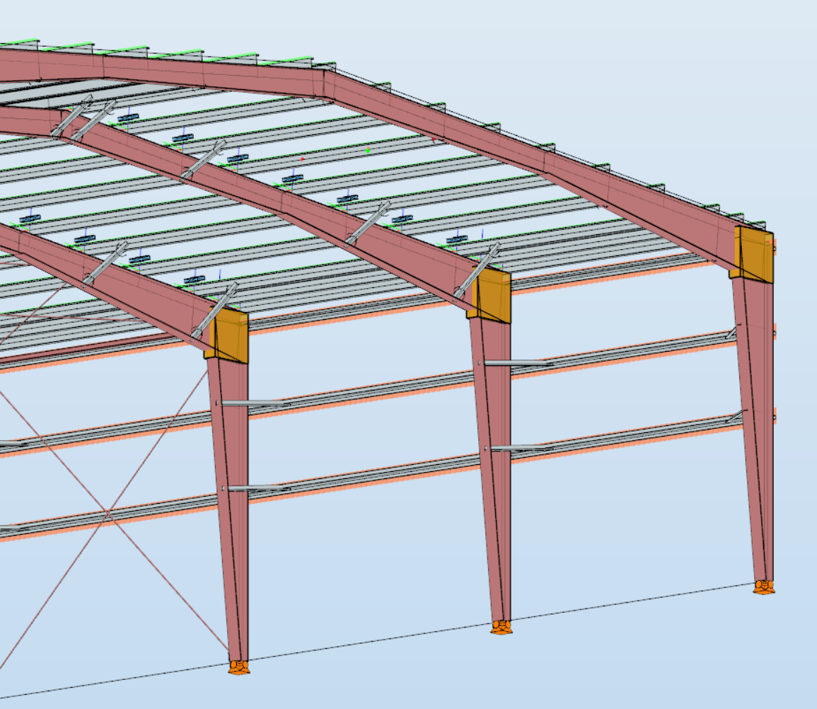
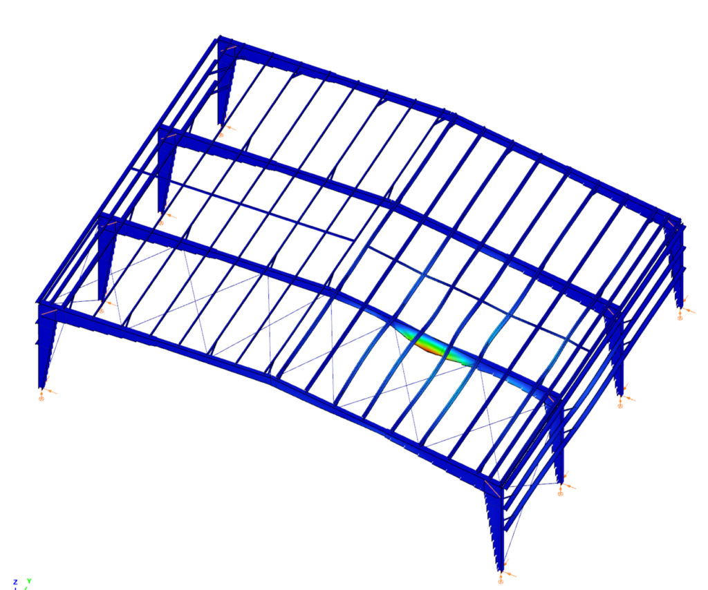
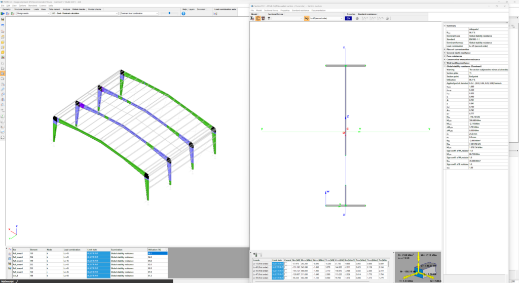
Did you know that you can use Consteel to design a pre-engineered Metal Building with all its unique characteristics, including web-tapered welded members, the interaction of primary and secondary structural elements, flange braces, shear and rotational stabilization effect provided by wall and roof sheeting?
Download the example model and try it!
Download modelIf you haven’t tried Consteel yet, request a trial for free!
Try Consteel for free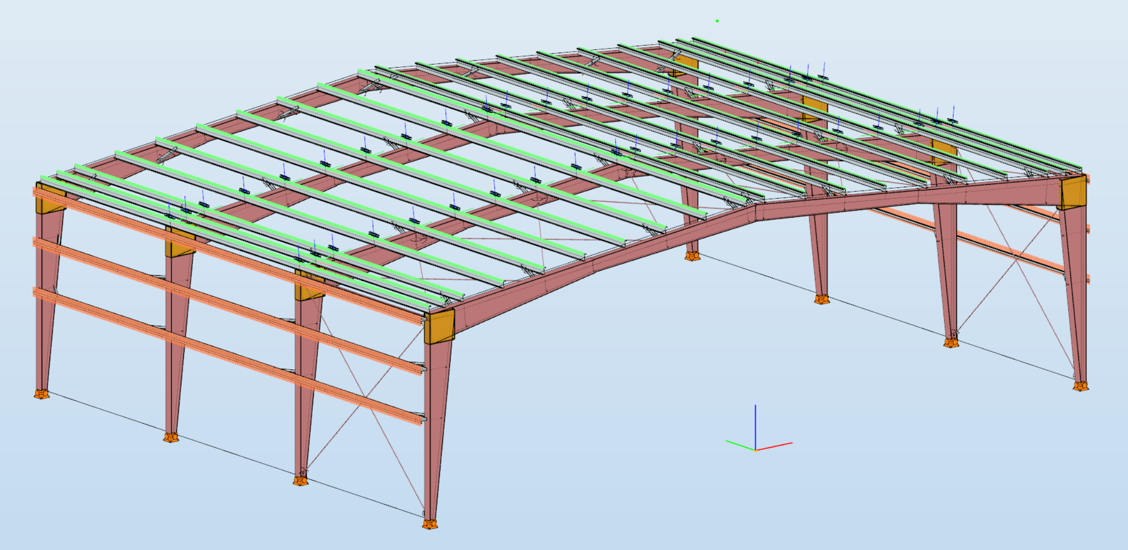
Consteel is a powerful analysis and design software for structural engineers. Watch our video how to get started with Consteel.
Contents
- Load sections
- Creating beams and columns
- Place supports
- Haunch definition
- Frame corner definition
Introduction
In Consteel there is a possibility to perform a model check on the structure to reveal modelling errors. This model check or diagnostics can be separated to First and Second level model diagnostics.
How it works
The First level diagnostics runs automatically before starting the analysis. It contains two types of checks. First a quick check is running which verfies the minimum conditions of creating the finite element mesh. The second one is a geometrical check performed on the generated finite element mesh verifing for example if the loads and supports are actually on the structure or if there are overlaps between bar or surface elements.
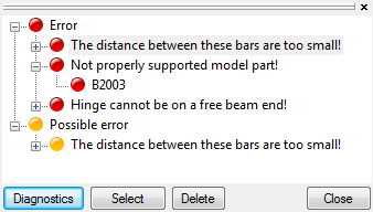
The Second level diagnostics can be initiated manually at any time during the modelling stage to examine the current state. The function can be launched by clicking onView/Diagnostics…button. It starts also with the same quick check as the first level. Then a basic check is running examining e.g. too small distances between members or unproperly supported model parts.
It is recommended to perform second level diagnostics after the modelling of the structure to reveal errors coming from inaccuracies of the modelling. After these errors had been fixed, it is OK to proceed to the analysis, which will automatically trigger the first level diagnostics. If it still reveals model errors, it is easier to handle them if all of the problems from second level diagnostics had been fixed.
Diagnostic messages
There are two kinds of diagnostic messages:
ERRORS: They make the calculations impossible or meaningless to execute so the detected errors stop further calculations.
POSSIBLE ERRORS: The warnings allow the calculation to run but they can influence the results.
By clicking on any of the object name in the tree structure and pressing the SELECT button, the selected object will be highlighted in the model graphical surface. The selected object can be erased by pressing DELETE button, or it can be modified with the regular geometric operations.
Tutorial video
To see the use of the diagnostic tool, please watch one of our earlier tutorial video below:
gateIntroduction
It happens quite often, that you need to import static models from another modeling software into Consteel. This is a very practical and effective solution to simplify your work. However, it is very important that the original model is accurate. If not, it could easily lead to unpleasant problems for the user.
How it works
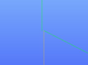
In the example given below, there was a very small distance between the endpoints of some of the columns.
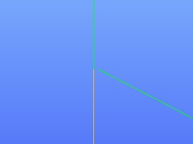
Consteel has an automatic correction algorithm that attempts to correct assumed modelling errors like this by merging nearby nodes. So the error correcting algorithm moves the top node of the column to the bottom node of the other.
After that, the column is no longer vertical. When running the analysis, there will be a message that “the columns are not exactly vertical”. It is only a warning message to inform you that your column is not vertical for some reason and it is up to you to decide whether or not to change that. If you decide to make the column vertical, you can do it easily. Please watch the video and follow the steps below.
gateThe portal frames composed of tapered welded I-shaped structural members play important roles in the industrial buildings. The application of the relatively thin plates and the optimized fabrication makes these structures being competitive against the light truss structures at least in the range of 24–36 meters span. Competition has resulted in lesser selfweights using thin plated slender cross-sections, which are sensitive to local buckling. However, the development of structures concerning local buckling was delayed in Hungary by the conservative specifications of the MSz 15024 standard. The application of the new EN 1993 standard may cause radical development in the design of tapered structural elements with relatively thin plates. This paper introduces the methods as well as the advantages of the new design methodology.
Clich the button below to download and read the full article. The article is in hungarian at page 42-55.
gate
