
Introduction
The workflow of engineers during the structural design process is rapidly changing nowadays. This change is mainly caused by the quick development of the engineering software tools which are trying to cover practically the entire design process. There is also an intense specialization direction of the developments, where more and more efficient software solutions are offered for more and more narrow and focused design phases. It creates a new situation for those design offices, trying to keep up with the technologies and increase their efficiency, that usually have several software tools for the different phases of their design workflow. However, the use of the most competent software for a certain phase is just one side of the coin, the whole process can only be efficient if these phases are suitably organized and connected. Theoretically, this is covered by the BIM approach, practically it highly depends on the quality of the interfaces between the different software tools. The optimal workflow is, however, not obvious even for a certain project, it is further influenced by several parameters like the size of the design office, the experience of the engineers, the local structural design regulations etc. Accordingly, it is still a far goal that a standardized process can unambiguously guide and govern the most efficient way of structural design processes. That is why it can be quite interesting to survey the recent situation, to find out how the engineers are actually working.
We made a survey asking more than 100 users of Consteel software from 6 countries (Hungary, Poland, Greece, Germany, Spain, Romania) about their typical structural design workflow. In the followings we present the results of this survey, discussing the model creating (geometry, model import, mechanical objects, connections), result exports, working model exchange and final model export issues.
Respondents
All the respondents are Consteel users, and the answers reflect their workflow in the structural design of various steel structures. The figures below show the characteristics of the respondents in terms of company size, project type, Consteel seniority.
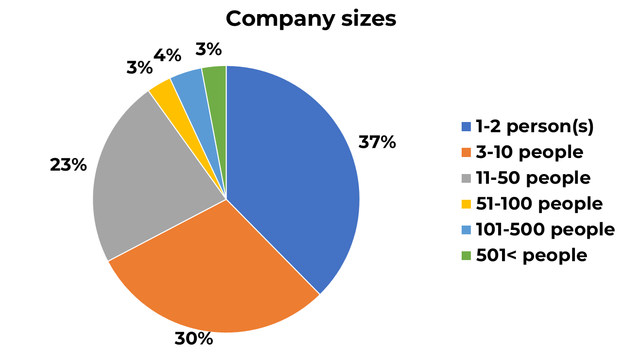
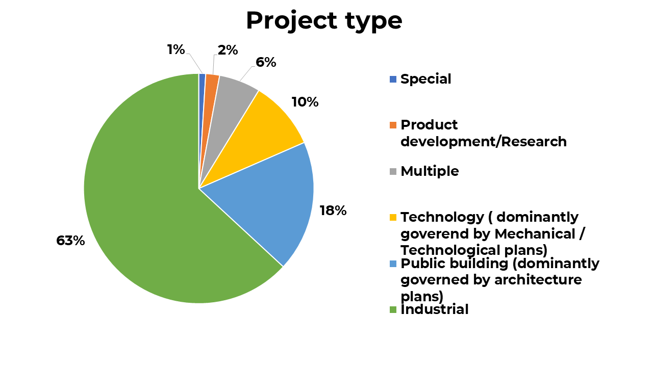
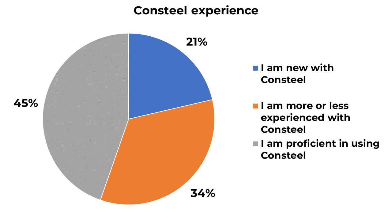
It is important to see that one-third of the respondents are very small or one-man companies, and the majority is from small or medium-sized companies. Most of the works are industrial projects (halls, industrial buildings) with some public and technology projects. Most of the respondents are proficient or experienced software users, some of them are starters.
Modelling the main structure
The creation of a global structural model suitable for the basic mechanical analysis and standard design calculations consists of two main phases:
- modelling the geometry of the real structural members with cross-sections, lines (beams, columns), surfaces (plates, slabs, walls)
- and definition of the abstract additional mechanical objects which are not part of the usual BIM model – loads, supports, connectivity of the structural members, eccentricities, dummy mechanical elements etc.
The results of the calculations on this global model are usually supplemented by additional structural design details such as connection design, foundation design etc. These design issues are generally performed by specialized software tools, the fit of the models of these tools into the whole BIM process is also an issue.
Starting with the geometry modelling the next figure shows the ways of creating the main geometry in Consteel. Half of the respondents do not use any import possibility and build the whole geometry in Consteel from scratch. Although the direct modelling is apparently still dominant, there is a considerable number of users applying the model import functionality and starting the modelling with receiving an existing model. Moreover, 10% uses only the model import, they probably created an efficient workflow for the model management where the model creation is done in a specific external (maybe parametric) software tool.

The next figure shows the types of software tools where the initial structural model import comes from. These tools are dominantly detailing, architecture or simple drawing software products. It is important to note that the detailing and architectural tools can provide much richer information about the model than the drawing software which usually yields only the line wireframe. But it is a very good sign that 4% of users create the initial model by scripting using some parametric software tool, this method can be regarded as a very advanced end efficient workflow for model management.

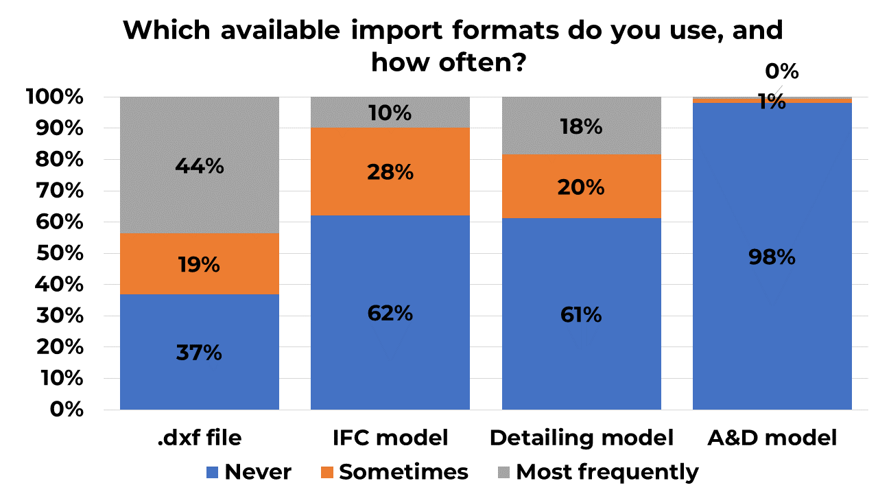
Continuing with the import possibilities the next figure shows the type of the import files/models. It is quite evident that the most frequently used import format is the dxf. (line model) file. The reason for that is most probably the simplicity of this format and accordingly the compatibility with almost all other software tools. However, this is the lowest level of interfacing option. More and more users receive their initial model from a detailing model file, which is a much higher-level import possibility, these models usually include the full member properties (material, cross-sections, eccentricities). The IFC format is also used but less often, because this type of format is not always suitable for the right definition of analysis models. Also important that the starting structural model in Consteel practically never received from another analysis and design software.
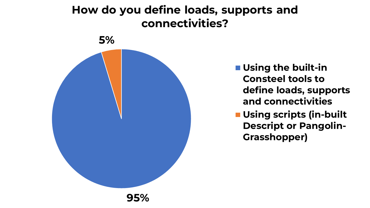
Once the members of the structural model are available, the model should be supplemented by the mechanical objects making the model suitable for structural analysis and design (supports, member connectivity, eccentricities, loads etc.). These additional modelling elements are predominantly created in Consteel, however, there are some (and hopefully growing number) users applying one of the several scripting options available (Descript – in-built scripting environment, Pangolin – scripting in Grasshopper) – see the next figure. We strongly think this is the future way of modelling making this process much more efficient and flexible to changes.
Modelling the connections
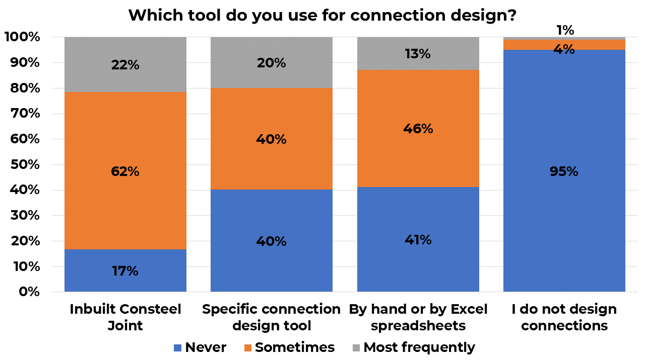
In the analysis and design of steel structures, the connections have usually great importance. First of all the design of the connections can take a considerable part in the whole process and sometimes the behaviour of connections has significant importance on the analysis and design of the structural members. From the next figure, it is clear that only a very small portion of the users are not designing the connections together with the main structure. Among the three types of applied tools, the most frequently used option is the inbuilt design tool of Consteel. It covers most of the connection types by standard calculations and has a complete interaction with the main structural model by automatic geometry, loading and stiffness transfer. There are more and more specific tools, used for the connection design, these are usually used for the design of more complicated and irregular connections. However, a considerable number of engineers are still using hand calculations or own developed Excel spreadsheets for connection design.
Exporting the results
After performing all the necessary analysis and designing or optimizing the structural elements there will be a model stage – at least in a certain phase of the design workflow – which provides inputs for the forthcoming design activities (like additional or supplementary analysis and design, detailing of the final structure, etc.). There are usually two types of supplying data for further work: (1) exporting certain numeric part of the calculation results, (2) exporting the whole structural model.
Exporting the calculation results
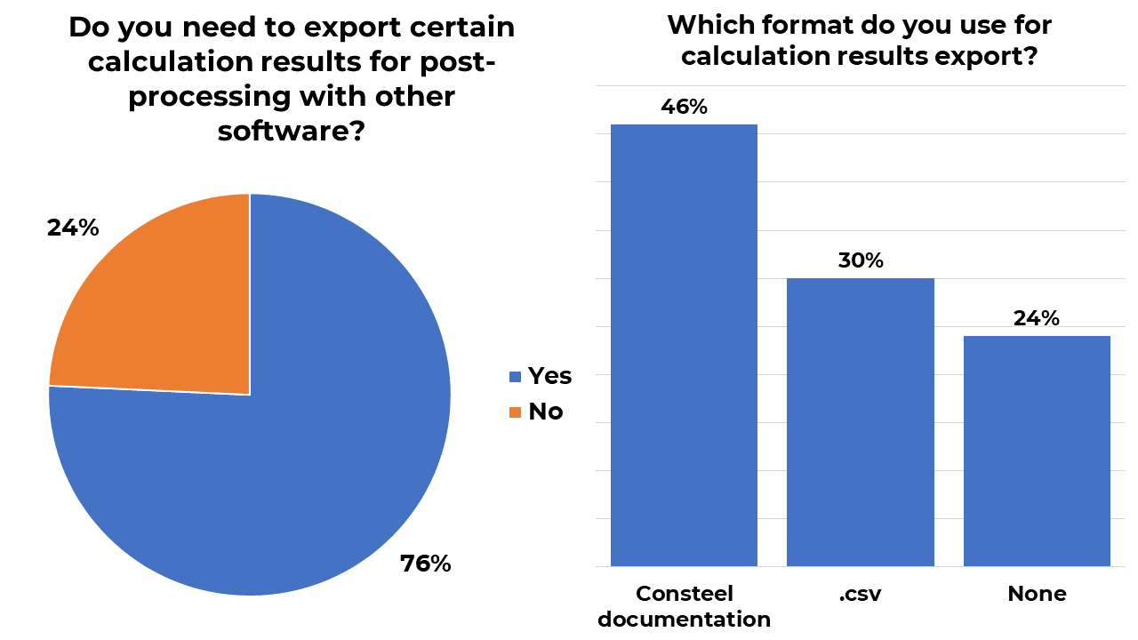
In the next figure, it can be seen that three-quarters of the users need to supply their calculation results to input additional calculations. It again proves the increasing fragmentation of the workflow by using specialized software for different calculation needs and the necessity for collaboration between these tools. It should be noted that the export of the pure calculation results (without the model) is a low-level workflow, compared to the whole model export (possibly including the necessary results). But this data provision is still heavily used due to the non-existing or insufficient communication between the different calculation software models. The format of the calculation results export is dominantly the forms of Consteel documentation which can be easily transferred to Word. Also, the tabular numeric results are exported to .csv as a simple and easy interface with many specific supplementary calculation tools.
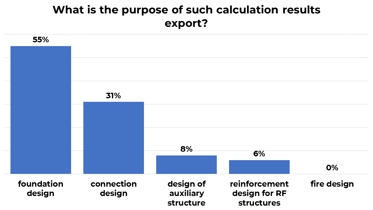
The purpose of the calculation data supplying is generally the foundation and the connection design. These design topics are usually efficiently handled by specialists with specialized software tools.
Exporting the whole structural model
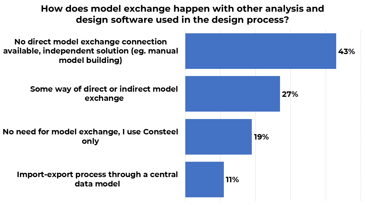
A more complete data provision is when the whole calculated and optimized model is exported to other applications. During the design work, the need for complete model exchange with other calculation tools can arise frequently. As it was mentioned earlier it is usually the least resolved issue since the very high number of different analysis and design packages and tools with generally no complete and sufficient direct model exchange possibility and no widely accepted and used specific central database (like IFC for architecture and BIM). That situation is illustrated in the next figure showing that the manual model building (or some other but independent model creation) in other applications is still dominant. But here again, there are signs of use of modern technics with some way of direct or indirect model exchange (sometimes through an intermediate neutral software) and 10% use a (usually own created) central data model for the import-export.
When the structural optimization is finalized – at least in a certain phase of the whole project – the finished model together with its calculation results is the most important documentation of the design work. This final model is a valuable source for the further work phases, these are illustrated in the next figure. While one-third of the users do not use the model for final data export (they use only the model and result documentation) the others export the final model mainly for the detailing process or visualization supplementing the documentation.

Conclusions
A comprehensive survey was made with the users of Consteel on their usual workflow in the structural design. Considering the characteristics of the respondents and project types, it can be seen, that we are in the middle of a big change in the structural design workflow. This is obviously supported and also constrained by the available solutions and tools. While there is still a significant portion of engineers using the old ways of structural design workflow with separated use of software tools supplemented by significant manual calculations; a considerable group is open to the modern methods governed by model parametrization, scripting methods for custom modelling and optimization and interfacing between different software solutions.
Thanks for the contribution to this survey goes to Strenco, Ergocad, Construsoft, Consteel Deutschland, and Gordias!