Did you know you can use Consteel to run second-order and buckling analyses on specific parts or elements of your model by defining a Custom Portion for the portion of interest?
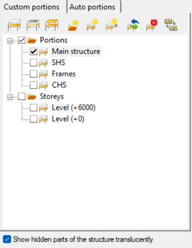
The workflow starts in the Portions Manager, where you can manually group structural members, frames, columns, beams, bracings into Custom Portions. These are fully user-defined and, importantly, only these custom portions can be directly used for analysis. This allows you to isolate exactly the structural subsystem you want to investigate, without being constrained by the full model.
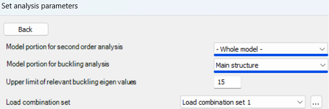
Once a portion is defined, it can be selected in the Analysis Settings, where you can choose whether second-order and buckling analyses should be performed on the entire model or only on the selected portion. The solver will then consider only that subset of elements when assembling the stiffness matrix and evaluating stability behavior.
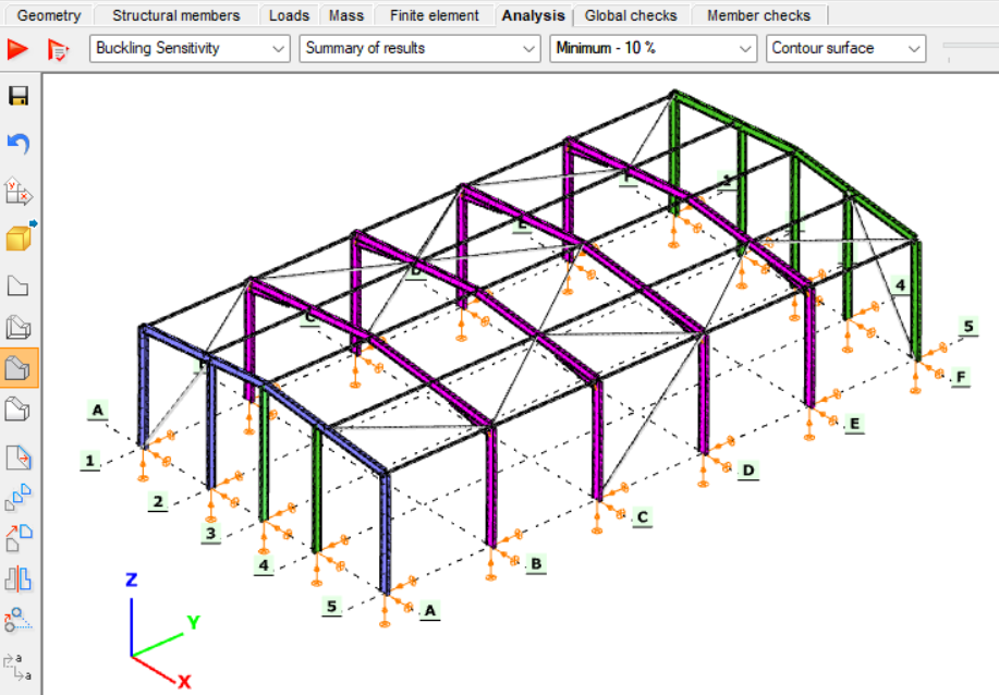
Running these analyses on specific portions has clear engineering advantages. Second-order effects and buckling phenomena are often governed by local structural behavior, such as a critical frame, a bracing system, or a column group, rather than the entire structure. By isolating these regions, you can:
- reduce computational effort and analysis time, especially for large models
- focus on the most critical load paths and instability mechanisms
- perform faster iterations during design refinement
- avoid unnecessary influence from non-relevant parts of the structure
This targeted approach leads to more efficient and controlled stability analysis, particularly when investigating sensitive or highly utilized structural components.
Download the example model and try it!
Download modelIf you haven’t tried Consteel yet, request a trial for free!
Try Consteel for freeIs a single dominant vibration mode sufficient, or should multiple vibration modes be considered in seismic analysis?
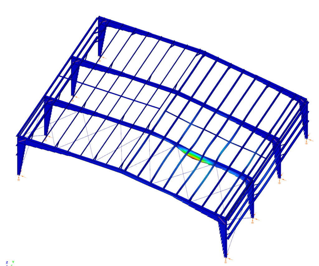
Steel portal frames are frequently used in industrial and logistics buildings as primary load-bearing structures. Their seismic behavior is strongly influenced by the stiffness of the roof diaphragm and by the interaction between the main portal frames and secondary structural subsystems such as endwalls.
In seismic design, engineers often assume that the global response of such buildings can be represented by a single dominant vibration mode. This assumption is valid when the roof diaphragm is sufficiently rigid and the first transverse mode mobilizes most of the structural mass. However, when the diaphragm is flexible or when different structural parts participate in different vibration modes, higher modes may also contribute to the seismic response.
This article investigates how the choice between a single-mode and a multi-modal approach affects the seismic design of steel halls modeled in Consteel. Through a comparative example, the study demonstrates the implications of different modal combination techniques and discusses how reliable internal forces can be obtained while maintaining compatibility with stability verification procedures according to EN 1993-1-1.
Case with a Rigid Roof Diaphragm
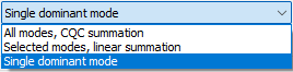
Single dominant mode
If a building is designed with a sufficiently rigid roof diaphragm, a single transverse vibration mode is typically able to mobilize close to 90% of the total participating mass. In such cases, the Single dominant mode method is an efficient and preferred design method.
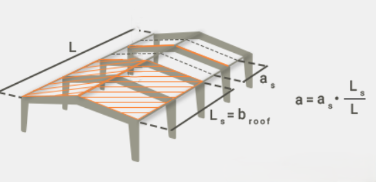
A rigid roof diaphragm can be achieved by:
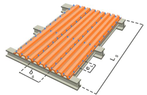
- Using an adequate trapezoidal steel deck, modeled in Consteel either
- as a Shear Field with a high shear stiffness parameter (“S” value), or
- by introducing equivalent dummy roof bracing diagonals with rod diameters calibrated to reproduce the diaphragm shear stiffness.
- Alternatively, real bracing elements may be added along the sidewall columns or from the eaves to the ridge along the building length.
Case without a Rigid Roof Diaphragm
If a rigid diaphragm is intentionally not assumed, a single vibration mode will generally not represent the full seismic response in the transverse direction.
Single dominant mode
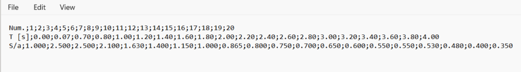
A dynamic eigenvalue analysis is first performed to determine the natural vibration modes of the structure. In Consteel, this analysis calculates the eigenfrequencies and corresponding mode shapes based on the structural stiffness and mass distribution, considering both the elastic stiffness and second-order geometric stiffness of the structure. The first three vibration modes are then evaluated for their mass participation in the transverse direction.
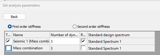
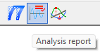
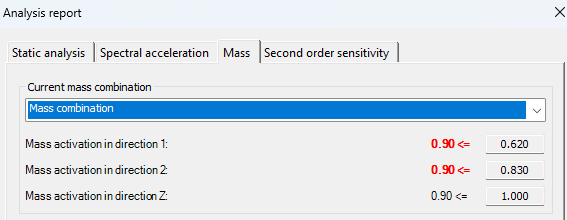
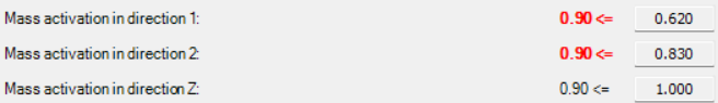
After the calculation, the mass participation for each principal direction (X, Y, and Z) can be viewed in the Analysis tab under the Analysis report, in the Mass section. In the examined case:
gateIntroduction
This article presents the calculation method for determining the buckling resistance of a pinned column with intermediate restraints in accordance with Eurocode standards. The procedure is based on an example from the Access Steel design examples collection and is compared with the calculation process implemented in Consteel’s steel member design functions, specifically within the Member Checks module.
In the following sections, a step-by-step guide is provided to demonstrate how the member check functionality can be applied to simple cases, highlighting both methodology and practical usage.
Input Data for the Example
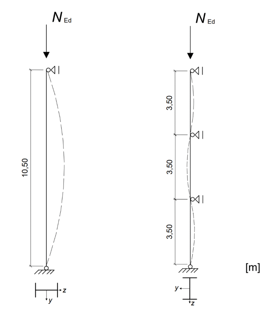
The example considers a pinned column in a multi-storey building, subjected to a design axial force of $N_{Ed}$ = 1000 kN. The column has a total length of 10.50 m and is laterally restrained about the y–y axis at intervals of 3.50 m.
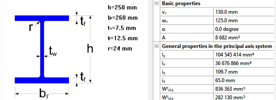
The member is a rolled HEA 260 section made of S235 steel. The cross-section is classified as Class 1. The geometric properties of the section are: height h = 250 mm, width b = 260 mm, web thickness $t_w$ = 7.5 mm, flange thickness $t_f$ = 12.5 mm, and fillet radius r = 24 mm. The cross-sectional area is A = 86.8 cm², with moments of inertia $I_y$ = 10450 cm⁴ and $I_z$ = 3668 cm⁴.
The material properties are defined according to EN 1993-1-1. Since the maximum thickness is less than 40 mm, the yield strength is taken as $I_y$ = 235 N/mm². The partial safety factors are γM0 = 1.0 and γM1 = 1.0.
Determining Design Buckling Resistance of a Compression Member
The design buckling resistance of the column $N_{b,Rd}$ is evaluated by determining the reduction factor χ for both principal buckling directions. This requires the calculation of the elastic critical forces $N_{cr}$, which form the basis for identifying the governing buckling mode.
Elastic critical force for the relevant buckling mode $N_{cr}$
The Young’s modulus is taken as $E=210000 \frac{N}{mm^2}$. The buckling lengths in the respective planes are $L_{cr,y} = 10.50m$ for buckling about the y–y axis and $L_{cr,z} = 3.50m$ for buckling about the z–z axis. Observe that the buckling lengths for the strong and weak axes differ according to the support conditions, which must be determined by the engineer in manual calculations.
$$N_{cr,y}=\frac{π^2*E*I_{y}}{L_{cr,y^2}}=1964.5 kN$$
$$N_{cr,z}=\frac{π^2*E*I_{z}}{L_{cr,z^2}}=6206.0 kN$$
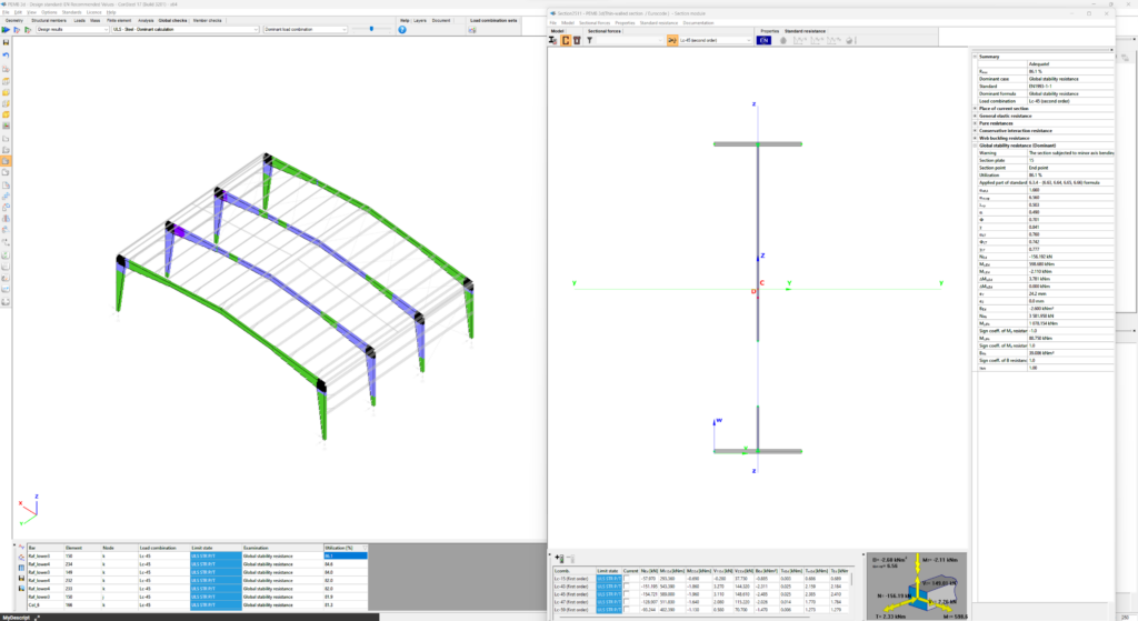
In Consteel, the elastic critical force for the relevant buckling mode can be determined using the Individual Member Design approach. This is accessible in the Member Checks tab under the Steel module, where selected members can be added and evaluated.

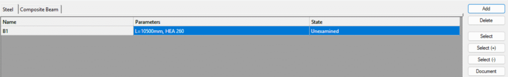
Once a member is selected, the analysis results are automatically loaded, provided that first- or second-order analysis results are available. Ensure that the analysis has been run in the Analysis tab and the cross section check on the Global ckecks tab before proceeding to the Member Checks section.
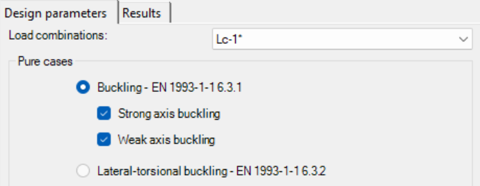
For the pinned column with intermediate restraints, the relevant buckling cases, strong and weak axis, are selected, and the dominant load combination is automatically indicated with a *. Consteel identifies the intermediate restraints separately for each direction and divides the member into segments accordingly to help determine the correct buckling lengths.
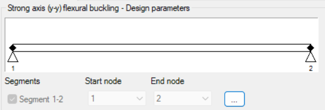
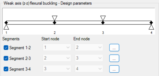
Design parameters for each segment are set with the three-dot icon:
At this step, users must verify the assigned values. By default, the first value is applied, and the correct buckling shape or effective length factor should be confirmed based on engineering judgment.
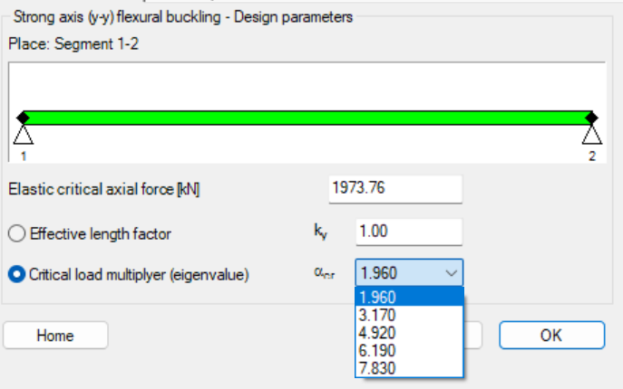
In order to use the critical load multiplier selection option, make sure to perform the calculation first:

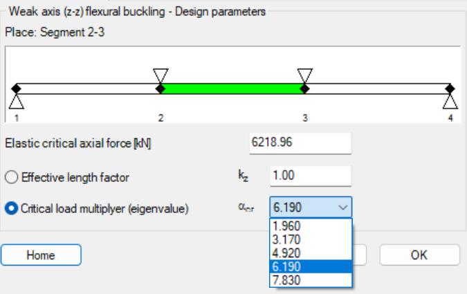
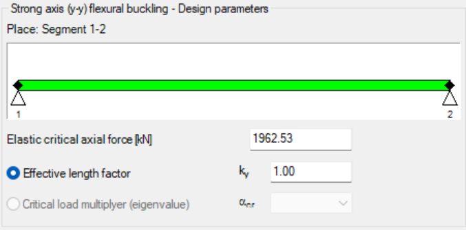
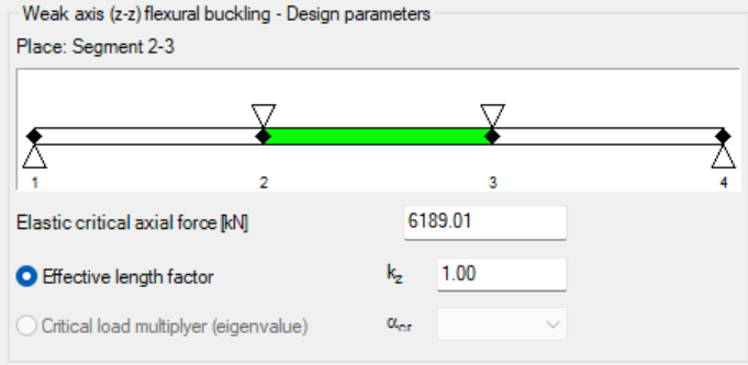
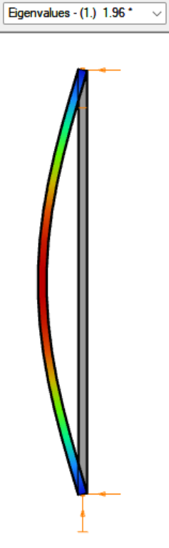
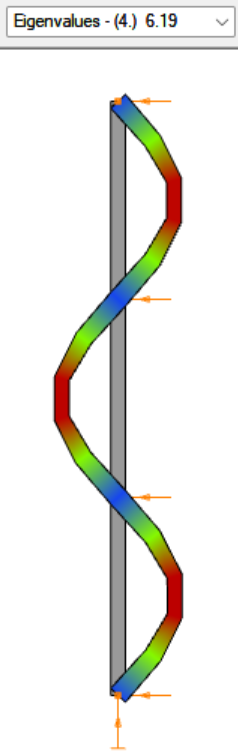
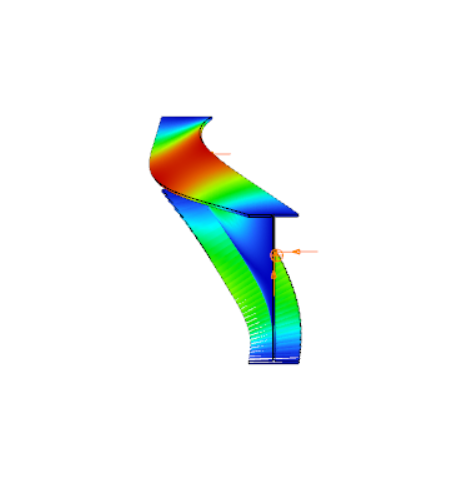
In order to check whether the correct critical load multiplier was selected, you can examine the effective length factor, which is calculated based on it (in this case, it is 1 for both directions). In our example, the relevant buckling shapes for the y–y and z–z directions are as follows:
The elastic critical force $N_{cr}$ is calculated automatically, regardless of whether the effective length factor was entered manually or the critical load multiplier was selected.
| Access Steel – manual calculation | Consteel using the effective length factor | Consteel using the critical load multiplier | |
| $N_{cr,y}$ | 1964.5 kN | 1962.53 kN | 1973.76 kN |
| $N_{cr,z}$ | 6206.0 kN | 6189.01 kN | 6218.96 kN |
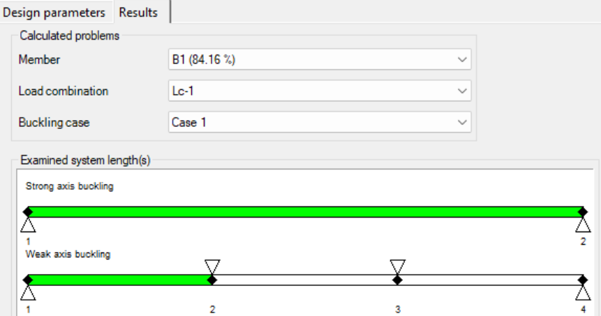
Once all parameters are defined, the design check is executed by clicking the Check button, and the results are displayed.
Results can be reviewed and filtered by member, load combination, and buckling case. Lateral-torsional buckling checks follow a similar procedure, with segment boundaries adjustable and critical moments calculated either analytically or using the critical load multiplier.
Non-dimensional slenderness
In order to determine the reduction factor, the non-dimensional slenderness λ must be calculated based on the elastic critical force corresponding to the relevant buckling mode.
$$\overline{\lambda_y} = \sqrt{\frac{A*f_y}{N_{cr,y}}}=\sqrt{\frac{86.8*23.5}{1965}}=1.016$$
$$\overline{\lambda_z} = \sqrt{\frac{A*f_z}{N_{cr,z}}}=\sqrt{\frac{86.8*23.5}{6206}}=0.573$$
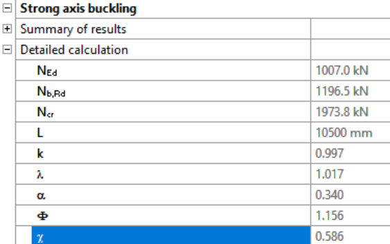
In Consteel, the detailed calculations for strong and weak axis buckling can be reviewed separately on the Results tab:
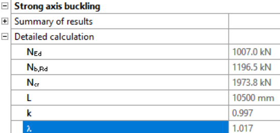
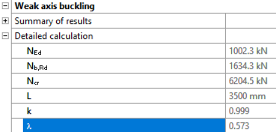
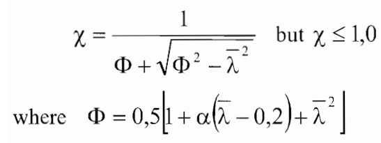
Reduction factor
For axial compression, the value of χ corresponding to the relevant non-dimensional slenderness $\overline{\lambda}$ should be determined from the appropriate buckling curve in accordance with EN 1993-1-1 §6.3.1.2.
For $\frac{h}{b}= \frac{250mm}{260mm} = 0.96 < 1.2$ and $t_f = 12.5 mm< 100 mm$
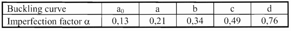
- buckling about axis y-y, buckling curve b, imperfection factor $\alpha=0.34$
$$\varphi_y=0.5*[1+0.34(1.019-0.2)+1.019^2]=1.158$$
$$\chi_y=\frac{1}{1.158+\sqrt{1.158^2-1.019^2}}=0.585$$
- buckling about axis z-z, buckling curve c, imperfection factor $\alpha=0.49$
$$\varphi_y=0.5*[1+0.49(0.573-0.2)+0.573^2]=0.756$$
$$\chi_y=\frac{1}{0.756+\sqrt{0.756^2-0.573^2}}=0.801$$
$$\chi=min(\chi_y;\chi_z)$$
$$\chi=0.585<1.00$$
Design buckling resistance of a compression member
$$N_{b,Rd}=\chi*\frac{A*f_y}{\gamma_{M1}}=0.585*\frac{86.8*23.5}{1.0}=1193 kN$$
$$\frac{N_Ed}{N_{b,Rd}}=\frac{1000}{1193}=0.84<1.00$$
Conclusion
This example demonstrates the application of the isolated member approach for a simple compression member. For more complex cases or alternative stability verification methods, such as the imperfection approach or the general method, refer to the dedicated article on stability design methods, where their principles and applications are discussed in detail.
Download modelDid you know that bar members can be included in load distribution even when slightly offset from the surface, by using a Load Transfer Surface with a user-defined tolerance?
A Load transfer surface (LTS) is a special type of surface that converts surface loads into line loads and distributes them to structural members. This is particularly useful when surface loads, such as floor loads, snow loads, or wind loads, need to be transferred to supporting members.
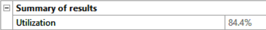
In order to use the meteorological load generator function or our fluid-dynamics-based universal wind load generation tool, FALCON, the load transfer surfaces (LTS) on the structure must intersect, they must meet along a common edge. Otherwise, the results will not be accurate.
This creates a problem when, for example, the purlins take over the meteorological loads from the sheets or panels, but their planes do not intersect. In this case, the LTS is applied to the plane of the main structure, while the members assigned to it may lie within a specified distance from that plane.
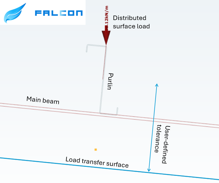
To define the tolerance for the load transfer surface, first go to the Options menu. There, you can set the maximum allowable distance between the bar members and the load transfer surface. In this example, all members that are less than 1000 mm from the surface can be assigned to the load transfer surface.
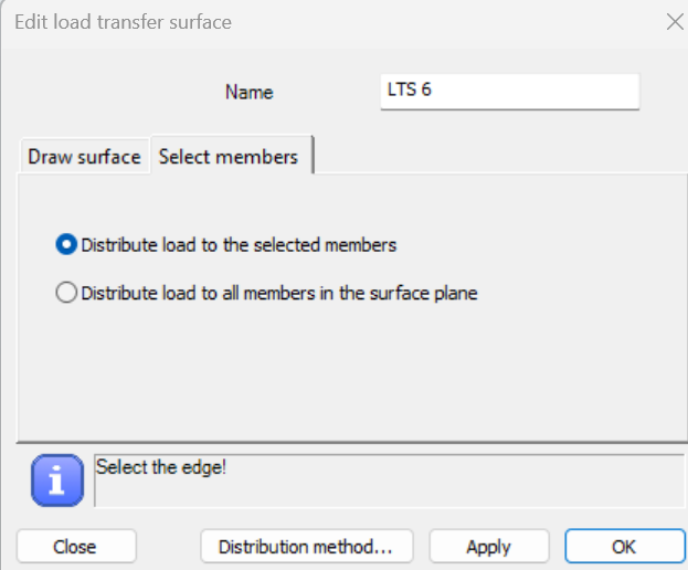
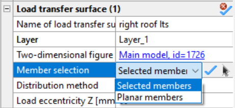
In order to be able to manually select the members attached to the load transfer surface, when defining it, make sure that in the Select members section you choose the Distribute load to the selected members option. If this option was not selected initially, you can set it later by selecting the surface and defining the member selection in the Object Properties window.
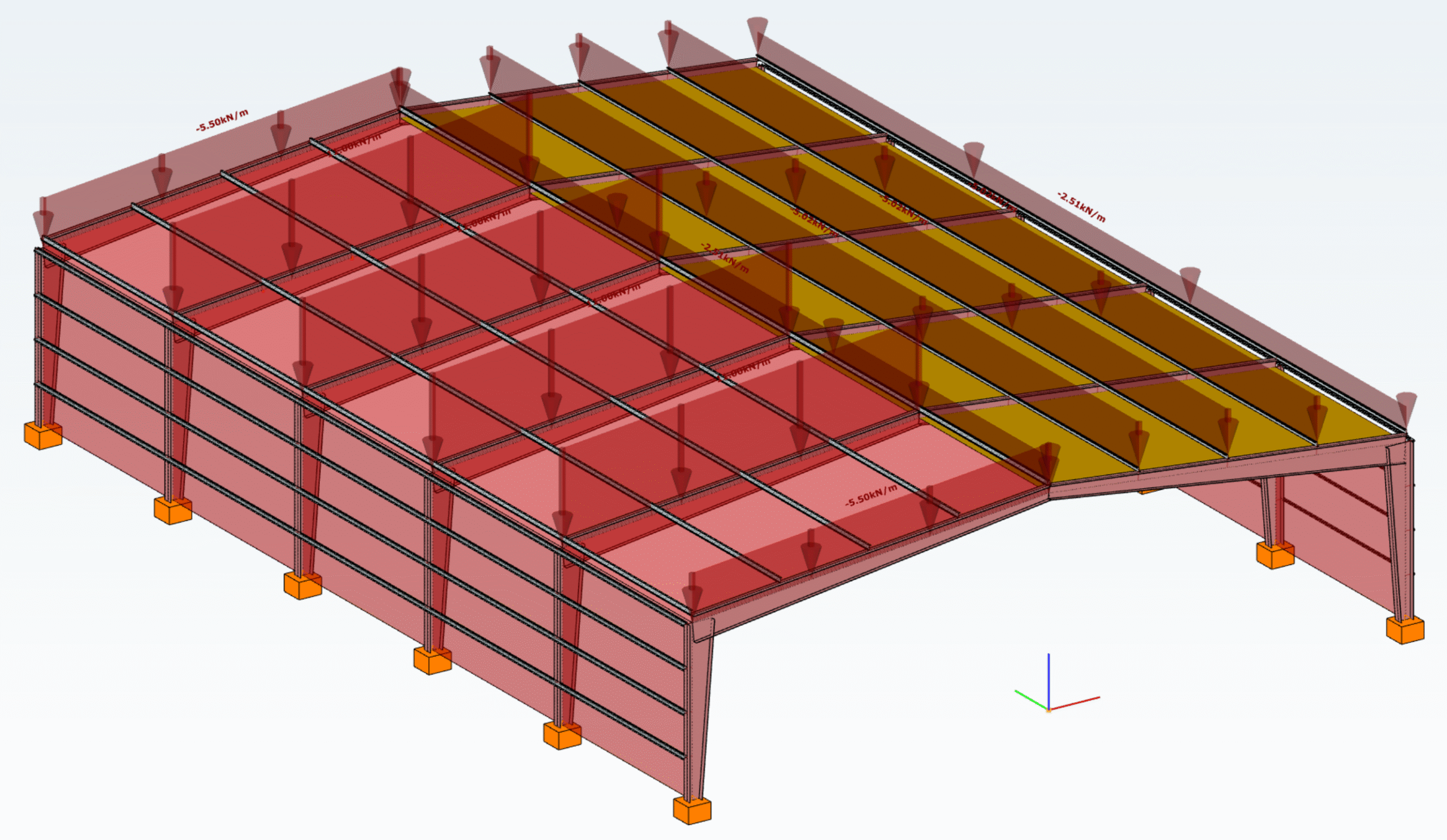
In the example model below, observe how the load distribution changes from the main beams (left side) to the tops of the purlins (right side) by introducing a user-defined tolerance and assigning the appropriate members to receive the load from the roof.
Download the example model and try it!
Download modelIf you haven’t tried Consteel yet, request a trial for free!
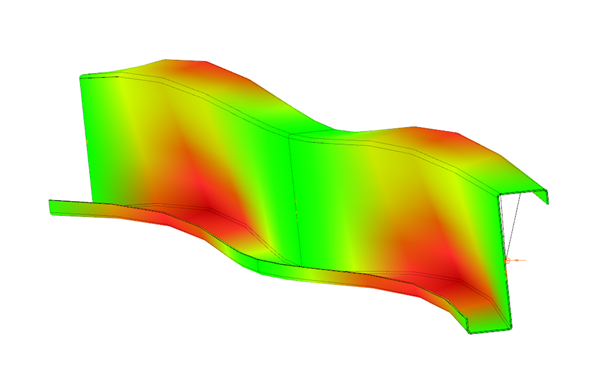
Try Consteel for freeConsteel recommends to use the General Method from EN 1993-1-1 for the evaluation of out-of-plane strength of members and sturctures. In addition, the scaled imperfection based 2nd order approach is available.
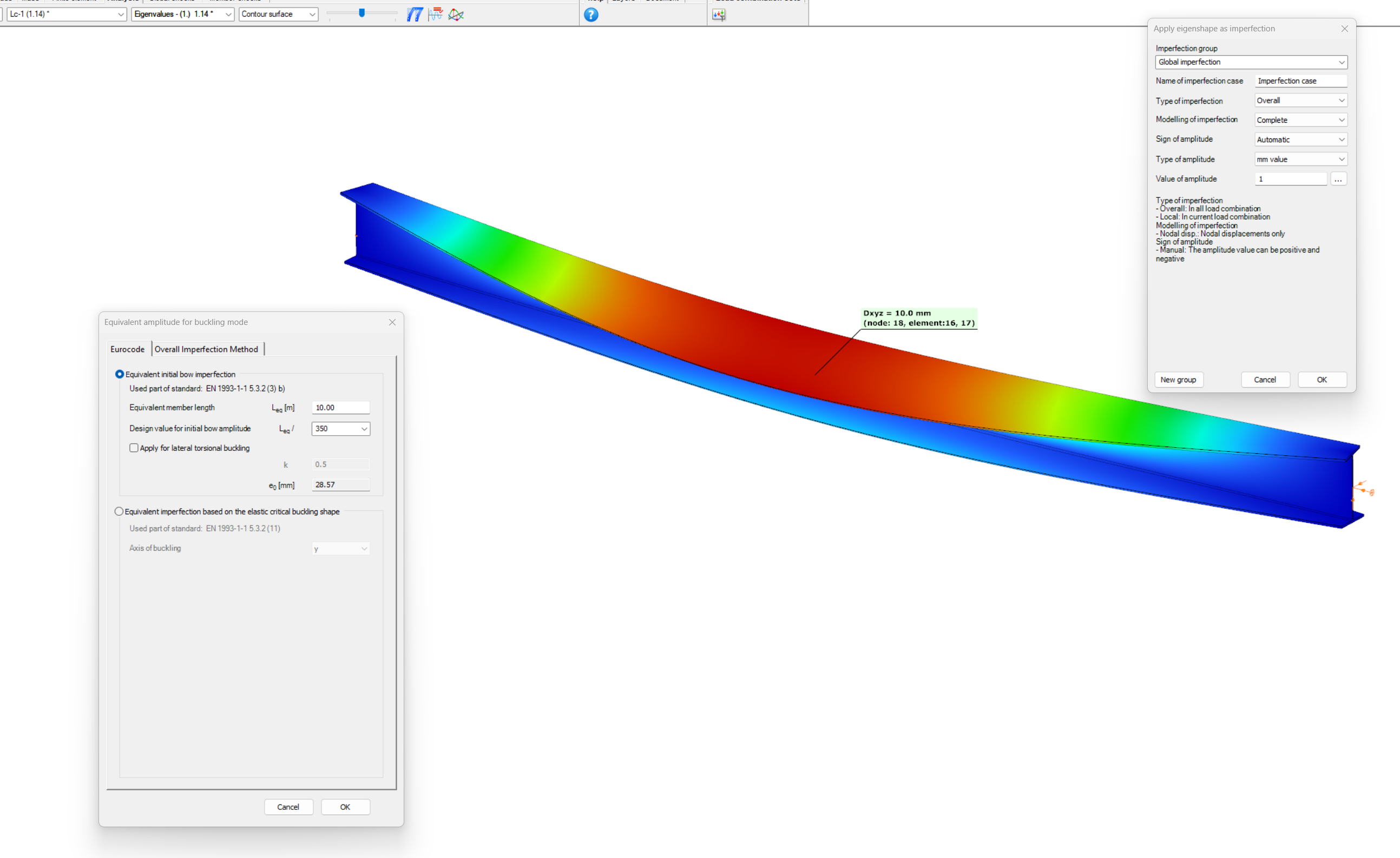
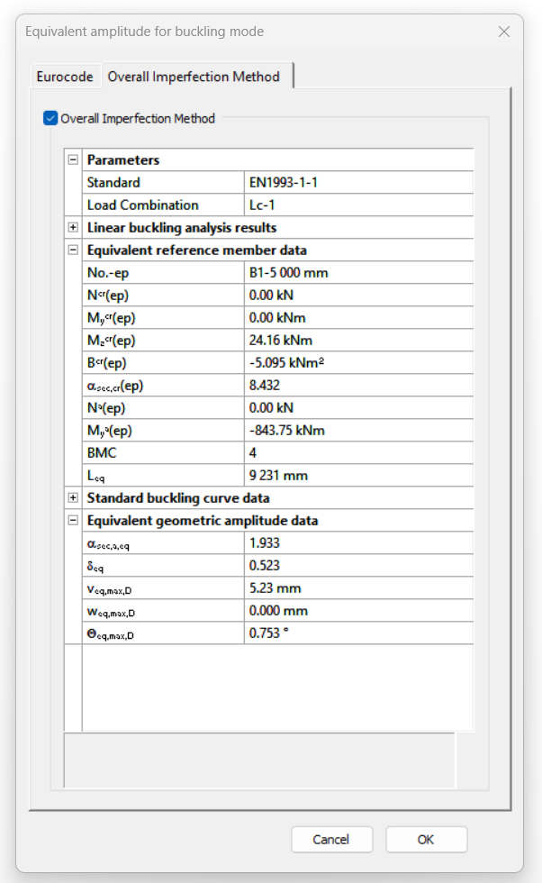
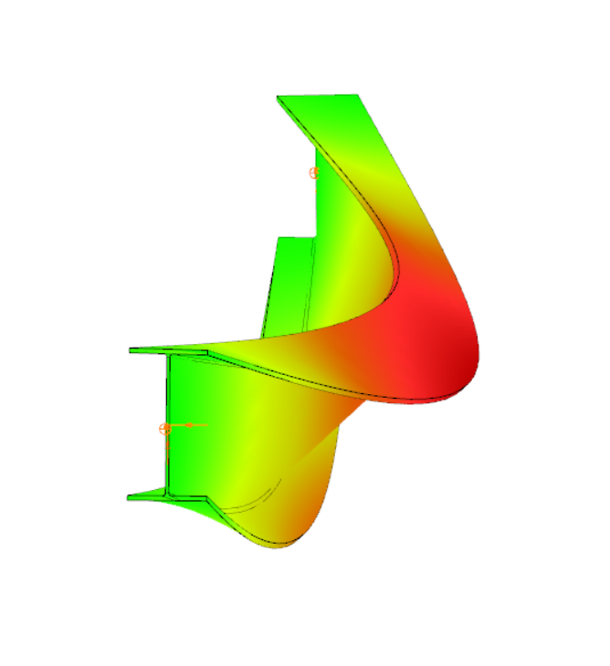
Did you know, that when linear buckling eigenform affine imperfections are used, Consteel can scale automatically the selected eigenmodes to perform a Eurocode compatible design? And you can even combine several imperfections?
Download the example model and try it!
Bending:
Download modelCopmression:
Download modelIf you haven’t tried Consteel yet, request a trial for free!
Try Consteel for free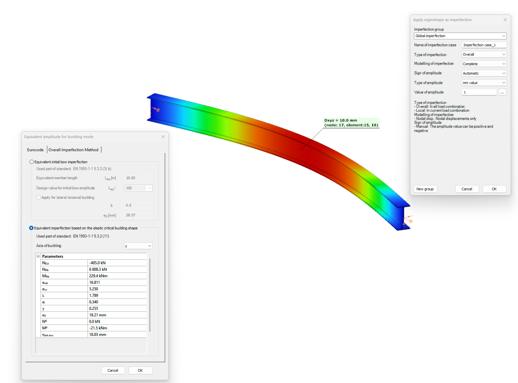
Have you ever heard about the ‘General Method’? This is an alternative design method to consider the interaction of axial compression with major-axis bending for general buckling situations, where the main interaction formulas are not applicable.
This basically includes every member with monosymmetric or asymmetric cross-sections or with cross-sections not uniform along the length (welded tapered sections) or laterally stabilized by sheeting or anything else without providing full fork supports.
Did you know, that the General Method is fully supported by Consteel and provides an automated buckling verification possibility? Of course, for the use of the General Method in a general case the traditional 12DOF beam finite elements are not applicable. But the special 14DOF beam elements used by Consteel are perfectly compatible?
Download the example model and try it!
Download modelIf you haven’t tried Consteel yet, request a trial for free!
Try Consteel for free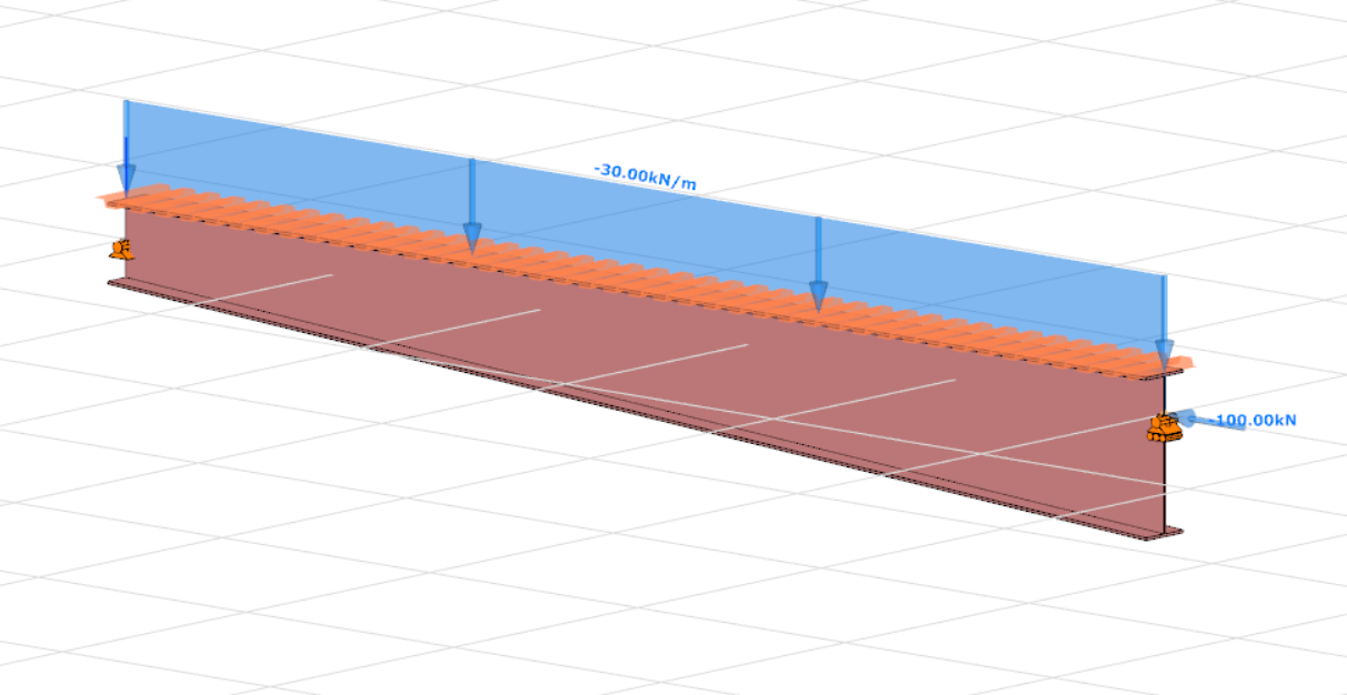
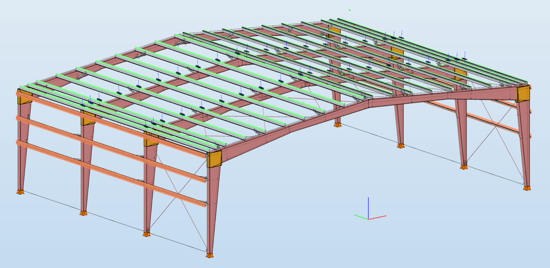
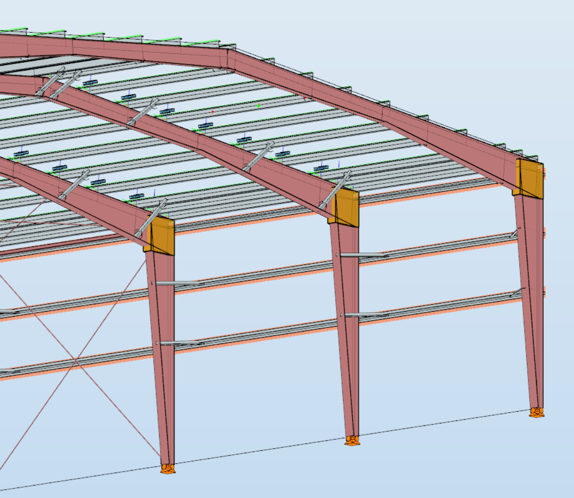
Did you know that you can use Consteel to design a pre-engineered Metal Building with all its unique characteristics, including web-tapered welded members, the interaction of primary and secondary structural elements, flange braces, shear and rotational stabilization effect provided by wall and roof sheeting?
Download the example model and try it!
Download modelIf you haven’t tried Consteel yet, request a trial for free!
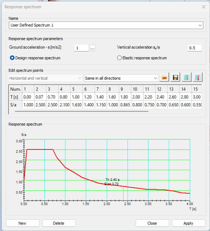
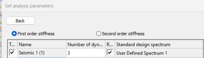
Try Consteel for freeDid you know that in addition the standard Type 1 and Type 2 response spectrums defined by Eurocode 8, you can use also user-defined spectrums with Consteel?
Download the example model and try it!
Download modelIf you haven’t tried Consteel yet, request a trial for free!
Try Consteel for free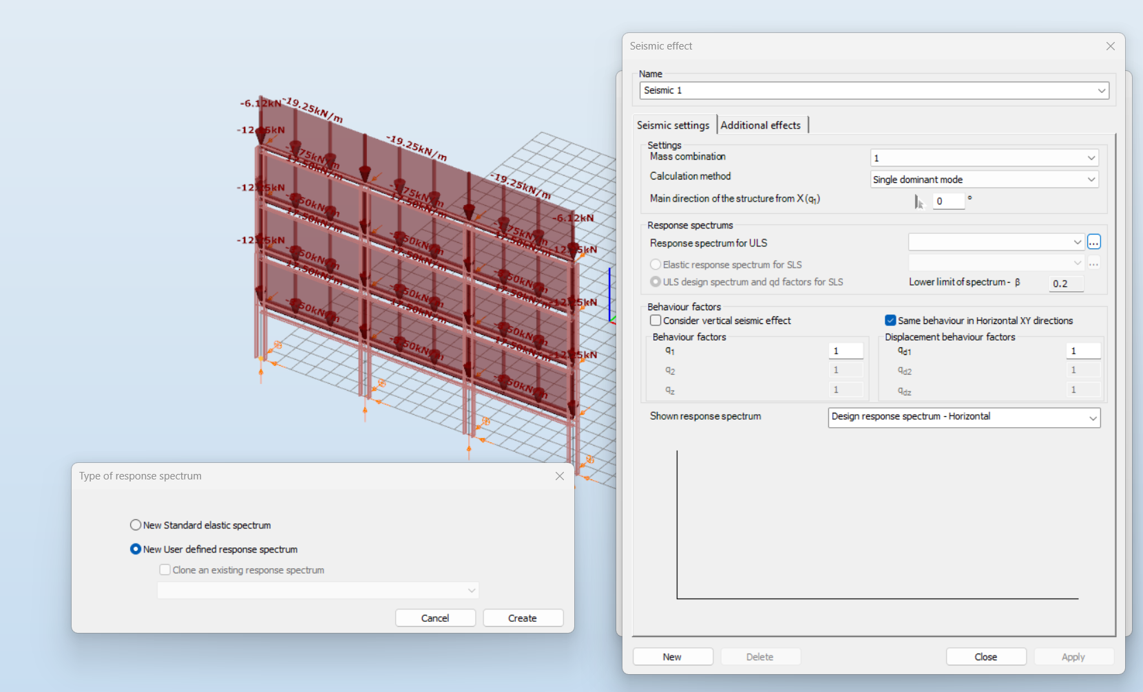

Did you know that you can use Consteel to design simple supported, continuous and over-lapped purlins systems in Consteel, considering shear and rotational stiffness of attached roof sheeting?
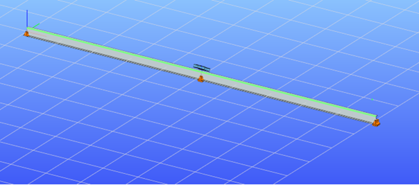
To use the purlin design functions, you first need to place cold formed Z or C purlins in your model, these are the only profile types supported for purlin design. All functions related to purlin lines can be found in the Structural members tab.

With these three main functions you can define the purlin line object, specify the support zones, and set the overlap zones. A detailed explanation of each can be found in the Consteel Manual – Purlins Chapter.
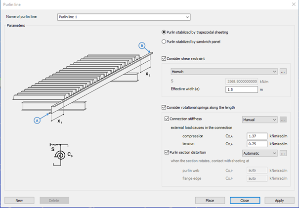
The Place purlin line function allows you to create and configure a purlin line object and place it precisely within your structural model.
You can also control the sheeting eccentricity in the Z direction, either by selecting predefined positions or by entering custom values. A graphical interface supports these settings to ensure intuitive and accurate placement.
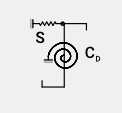
An important feature of this function is the ability to simulate the supporting effect of roof sheeting on the purlins. This is done by applying spring stiffnesses that reflect how the sheeting contributes to the overall structural behavior. Two types of springs are considered:
- Translational (shear) spring, representing the shear stiffness of the roof covering.
- Rotational spring, accounting for both the connection stiffness and profile distortion.
Depending on the selected sheeting type (trapezoidal sheeting or sandwich panels) the stiffness values can be entered manually or calculated automatically. Automatic calculations follow the guidelines of EN 1993-1-3, providing reliable and standards-based results.
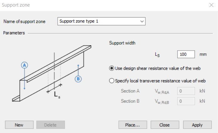
The Support zone function allows you to define the geometrical and mechanical parameters at the points where the purlins are supported. The geometry and bearing capacity can be set by specifying the support width and selecting how the load capacity is defined.
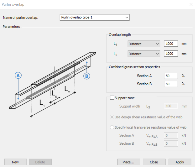
The Purlin overlap function helps define how individual purlins are connected in continuity. The standard (EN 1993-1-3) distinguishes between simple overlap joints and joints with coupling elements. Currently, only overlap joint is available in the program. You can define the length of the overlap either in millimeters or as a percentage of the member length. Additionally, the stiffness distribution between the two overlapping members can be adjusted.
Together, these functions ensure accurate modeling of purlin behavior, support conditions, and connection details, aligning with design standards and practical requirements.
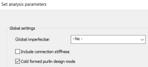
To ensure that all purlin line related objects are properly considered in the analysis, make sure to activate the Cold formed purlin design mode in the analysis settings. When this mode is enabled, both the buckling analysis and the global design are performed on a submodel that includes only those members associated with purlin line objects. This mode is intended exclusively for the design of the roof purlin system.
If purlin related objects are present in the model but the cold formed purlin design mode is not active, the structural elements connected to these objects will be excluded from the second-order stiffness matrix. As a result, their influence will not be considered during linear buckling or second-order analysis.
Download the example model and try it!
Download modelIf you haven’t tried Consteel yet, request a trial for free!
Try Consteel for freeDid you know that you can use Consteel to design pad foundations?
A pad foundation, also known as an isolated or spread footing, is a type of shallow foundation commonly used in industrial buildings to support individual structural elements such as steel or reinforced concrete columns. It transfers the concentrated loads from these elements to the bearing soil layer, distributing them over a larger area so that it can safely carry the load.
In industrial settings, pad foundations are designed to accommodate higher loads and, where necessary, additional effects from equipment or machinery, while keeping settlement within acceptable limits to ensure the structure’s stability.
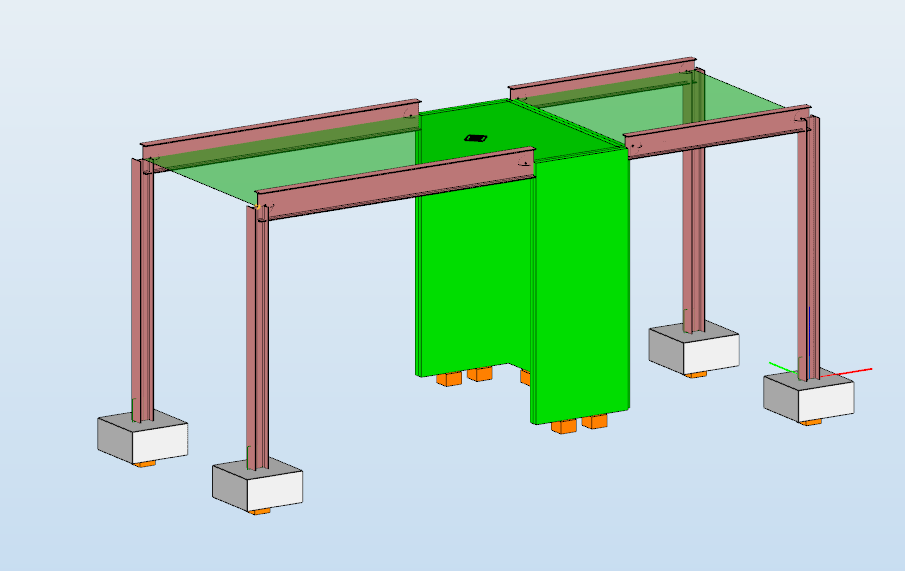
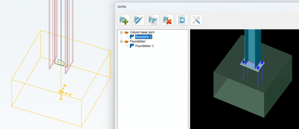
In Consteel, a pad foundation is defined through the Spread footing function as a specialized compound object used for modeling shallow foundations of individual columns.
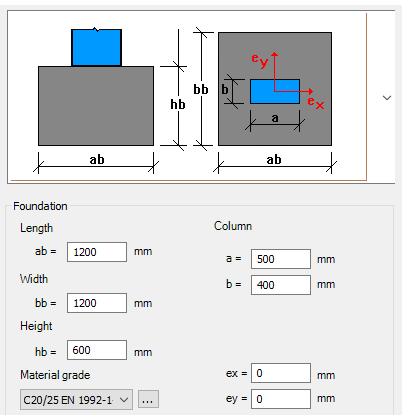
It consists of a bar member, a support positioned at the geometric center of the foundation base, and an associated joint model that defines geometry, material, and eccentricities. The reference line of the footing is always aligned with the global Z axis, and the element is typically placed at column nodes, where it can inherit eccentricities from connected members, enabling an accurate representation of load transfer to the bearing soil layer.
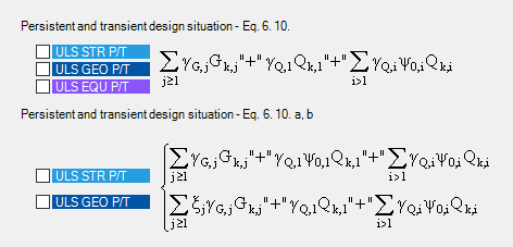
For the design of pad foundations, before starting, don’t forget to load the necessary load combinations into your model and perform the analysis for them. For the foundation design, at least one geotechnical ULS combination is required to verify soil bearing capacity and to check against sliding and overturning.
In the Joint module, designing a spread footing is simple and fully integrated. Once the foundation joint is created and placed at the column node, you can define its geometry, material, and reinforcement directly in the module.
More detailed instructions and options for defining dimensions, materials, and placement can be found in the Consteel manual.
Design loads can be imported automatically from the Consteel model, taking into account column eccentricities and forces from connected members. The module performs all necessary checks, including soil bearing, sliding, overturning, bending of the reinforcement, settlement, and punching shear.
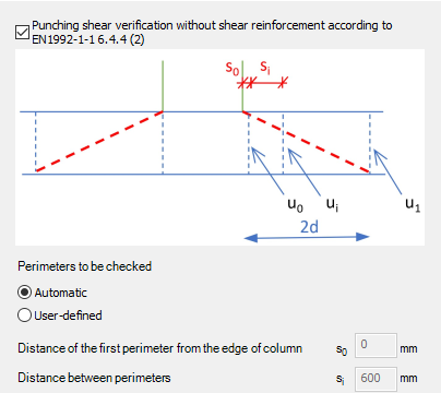
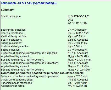
Results are displayed clearly, showing which checks pass and highlighting any areas that may need adjustment. This approach allows engineers to design foundations efficiently while ensuring compliance with Eurocode standards.
Download the example model and try it!
Download modelIf you haven’t tried Consteel yet, request a trial for free!
Try Consteel for free