Consteel offers a range of load combination filtering options, which can be applied based on limit states, load cases, and analysis and design results. By applying different series of filters, designers can streamline their workflow and reduce calculation time.
Filtering options
Filtering is realized through the Load combination set definition window.
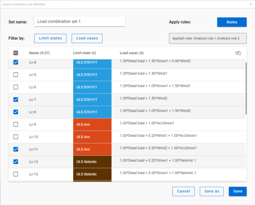
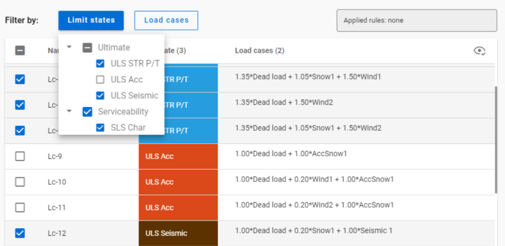
Filtering by limit states and by load cases are handled together with the checkboxes under the Limit states and Load cases buttons.
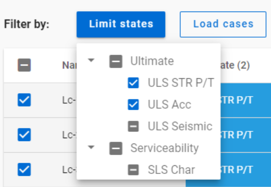
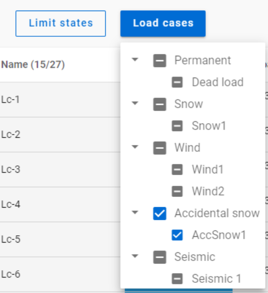
The 3-state checkboxes affect each other as they are not only used for selection but also for indication of the content. They can be manually set only to checked or unchecked. The middle state only appears when other filters are applied.
Filtering by limit states or load cases does not require any calculation results.
Filter by rules, on the other hand,is based on the actual analysis and/or design results. Different types of rules can be applied one by one or at the same time to select the desired load combinations.
When a rule is applied, all the load combinations that are selected on the Load combination set definition dialog- either with filtering by limit states/load cases or checked in manually- are examined at every position the rule indicates. Load combinations that meet the rule’s criteria are selected (remain checked in), while those that do not, become unchecked.
- With analysis rules, load combinations can be selected based on deformations or internal forces at either every finite element node or only at the member ends. This last one is included specifically for connection design. Deformations are checked in SLS combinations, internal forces are checked in ULS combinations only.
- With buckling rules, those ULS load combinations can be selected which have the elastic critical load factor (first buckling eigenvalue) less than the given limit.
- With design rules, load combinations can be selected based on utility ratios checked in every finite element node of the chosen portion. Utilizations are available from several design checks: dominant results and detailed verifications for steel elements such as general elastic cross-section check, pure resistances, interactions and global stability. Only ULS combinations can be filtered with design rules.
Interaction of the different filter types
Filtering by limit states, load cases, and rules can be used together, with rules being applied only to load combinations that are checked in and have the necessary calculation results.
Let’s see an example.
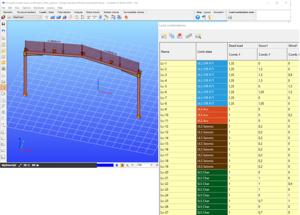
It is a simple 2D frame model, with 27 load combinations of various limit states generated. Analysis and design results are calculated for all load combinations.
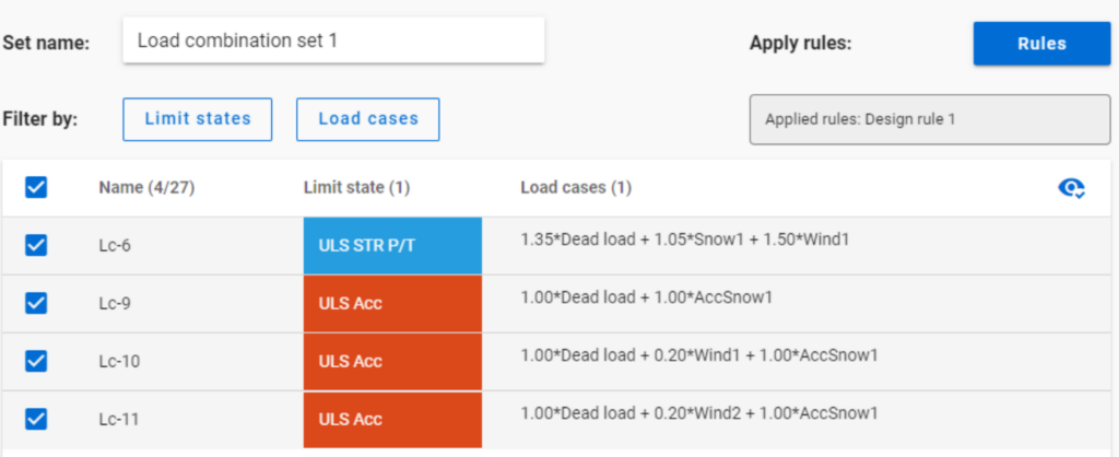
If applying design rule to select only those load combinations which result dominant utilization over 50%,
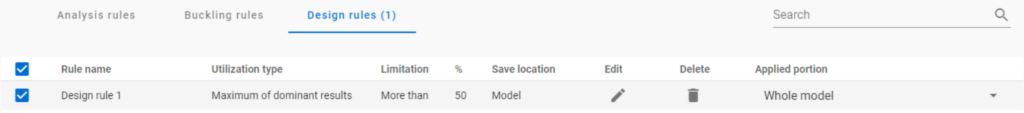
4 load combinations will be selected (Load combination set 1):
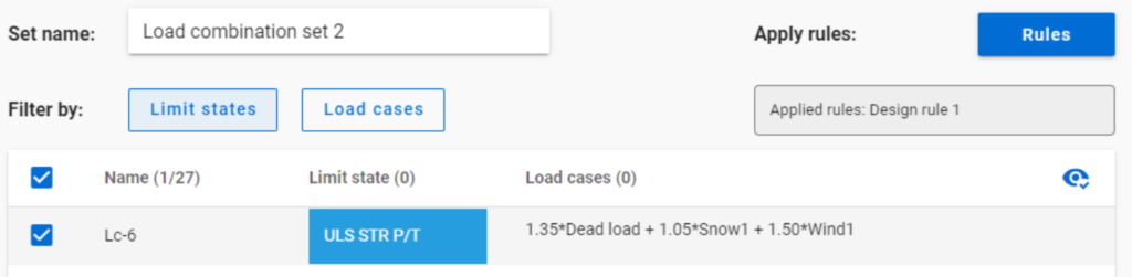
But if ULS Accidental limit state is turned off before applying the same 50% filter,
only one load combination is selected (see Load combination set 2).
Application of multiple rules
Applying multiple rules together results in the sum of the lists that would have been created separately.
gateIn Consteel 16, we introduced the function of load combination filter. Filtering is possible based on the load combinations’ limit state, load cases, and corresponding analysis and design results. The goal is to create different sets for the different steps of the optimization and reduce calculation time while making sure that all the relevant load combinations are considered. Let’s see what a conscious design workflow looks like in practice!
Description
It is a significant problem in almost all structural design projects that the standards define many possible load cases and combinations to evaluate. Although most of these load combinations are never relevant or provide decisive design situations, it is usually not evident which ones might be neglected safely, especially when considering, that different load combinations can be relevant for different parts of the structure, like primary or secondary structure, connections, etc. Accordingly, the optimization process is overloaded by a large amount of unnecessary calculations.
With the load combination filter function, a reduced list of load combinations aka a load combination set can be created and saved for the different steps of the optimization.
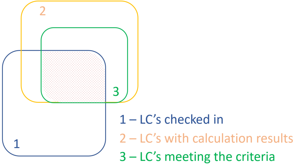
The optimal workflow for the filter may vary for the different purposes the sets are created for, but there is a recommended general process that can serve as the basis for all of them. First, run the simplest calculations and use the results for a rough selection which will already decrease the number of load combinations noticeably. Then one can increase the complexity of the calculations and further reduce the list of combinations by using stricter filters. If needed, this step can be repeated. This iterative process allows us to avoid complex and time-consuming calculations for all the thousands of load combinations.
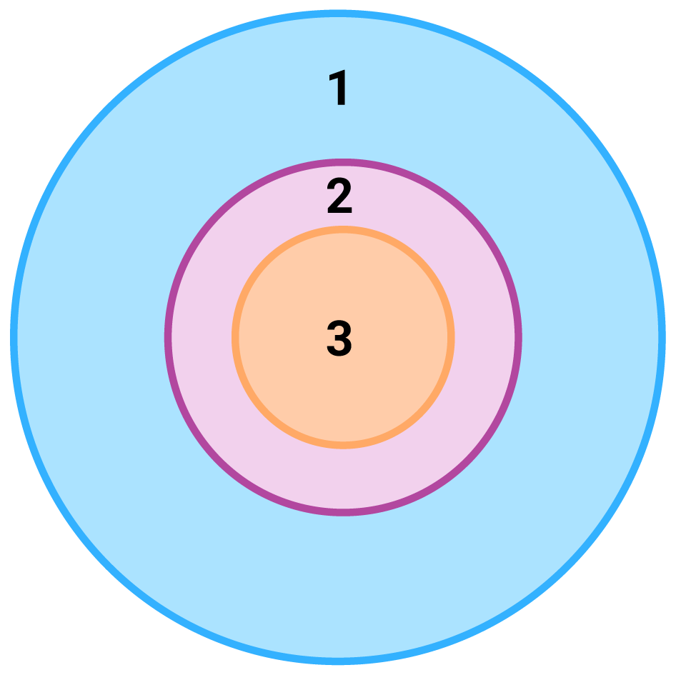
1 – all load combination, no filter;
2 – initial set with broad filter;
3 – working set with strict filter
Detailed process

Modeling
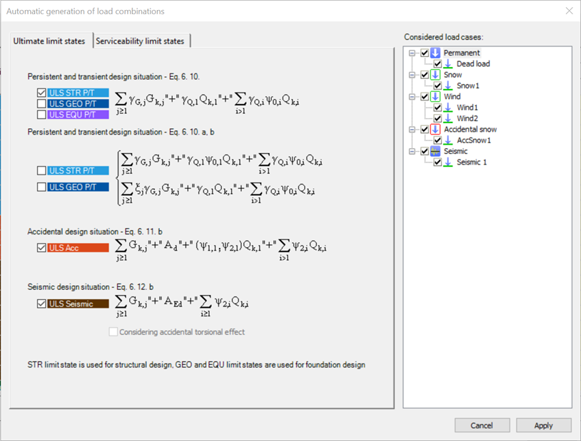
The base of all optimization processes is a correctly built structural model. So, the first step is geometrical and structural modeling and load definition. It is advisable to run a first-order analysis for only one or two load cases and diagnostics to find possible modeling errors. Load combinations can be created after that. Every limit state that will be used during the whole design of the structure, should be defined. Consteel’s automatic load combination generation function is an efficient tool to do it.
Calculation and filter
On the Load combination set definition dialog, it is possible to create load combination sets by selecting the combinations based on their limit state and/or the load cases they contain. But usually, filtering on specific analysis or design results will likely be more effective in reducing the number of combinations. Using the above-described general workflow, the steps are as follows:
gateFrom now, the new Project Center unites all the functionalities for model and account management, supplemented with easy access to personalized information and learning materials.
gateIntroduction
It is essential for the effective work of the design engineers to have a model which is easy to overview. In Consteel there are several functions to achieve that such as layers and portions, and also Member coloring by cross-section.
How it works
The color of the displayed objects is now determined by the object style settings in Options.
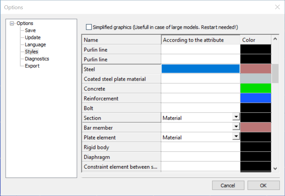
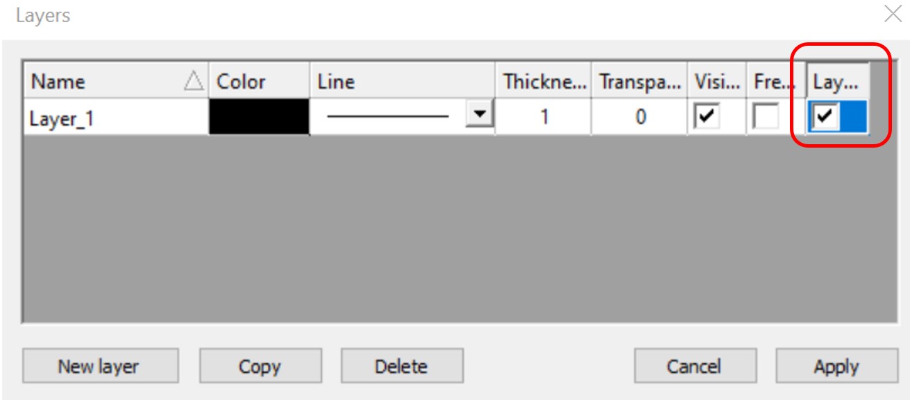
Layer color can overwrite these settings if the Layer style cell is checked on Layers dialog.
In the case of beam type members, it is also possible to set the color of the object according to the section it has defined. Coloring by member can be set with Object color setting dialog in the right bottom corner:
gateScripting is a powerful tool in your hand to create, access, and manipulate flexibly model objects and operations or calculations on them. We know it is not always easy or familiar to the structural engineers, so want to bring the power of scripting closer to you. The Consteel Programming Interfaces cover multilevel scripting options, one of them is the updated internal scripting environment, Descript.
gateModeling stiffeners in Consteel
With Superbeam feature in Consteel, modelling of stiffeners is easy and effective. Multiple options and various shapes are available. Analysis is possible with beam and shell elements either.
gateIntroduction
Are you wondering how a web opening would influence the lateral-torsional buckling resistance of your beam? Check it precisely with a Consteel Superbeam based analysis
It is often required to let services pass through the web of beams. In such cases the common solution is to provide the required number of opening in the webplate. Such an opening can have a circular or rectangular shape, depending on the amount, size and shape of pipes or ventilation or cable trays.
Beams must be designed to have the required against lateral-torsional buckling. The design procedure defined in Eurocode 3 is based on the evaluation of the critical bending moment value which provides the slenderness value, needed to calculate the reduction factor used for the design verification.
There is no analytical formula provided in the code for beams with web openings. Would the neglection of such cutouts cause a miscalculated and unsafe estimation of the critical moment value?
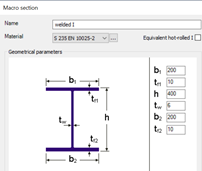
The following demonstration will be made with a 6 meters long simple supported floor beam with a welded section.

Exposed to a linear load of 10 kN/m, the critical bending moment value of the solid web beam can be obtained by performing a Linear Buckling Analysis (LBA) with Consteel.
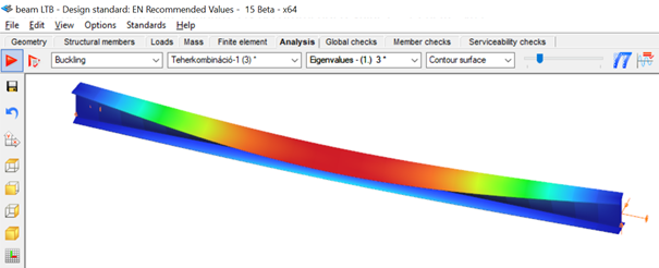
The obtained critical multiplier for the first buckling mode is 3.00 which means that the actually applied load intensity can be multiplied by 3.00 to reach the critical load level. The corresponding critical moment will have the value of Mcr = 3.0 * 47.18 = 141.54 kNm yielding a slenderness of 1.286 (Mpl,Rd = 234.20 kNm) and a lateral-torsional buckling resistance of 0.394 * 234.20 = 92.27 kNm. With this value the actual utilization ratio is at 51%.
How would this value change if a rectangular opening needs to be cut into the web of this beam?
Analytical formula for critical bending moment
By looking to the analytical formula (ENV 1993-1-1 F.4) to calculate the critical moment of double symmetric sections loaded at eccentric load application point it becomes obvious that the section properties having effect on the moment value are Iz, Iw and It.
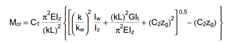
An opening in the web has no effect on the first two values and has very little effect on the last one. As it has been already shown in previous article, the presence of such an opening can have effect on the vertical deflection, but as long as the lateral stiffness of a beam is much lower than it’s strong axis stiffness, the vertical deflections can be neglected when the lateral-torsional buckling resistance is calculated. The usual linear buckling analysis (LBA) performed also by Consteel neglects the pre-buckling deformations.
Therefore one can expect that in general web openings can be disregarded when the critical moment value is calculated.
Analysis with Consteel Superbeam
Beam finite elements cannot natively consider the presence of web openings. In order to obtain the precise analysis result, it is possible to use shell finite elements. The new Superbeam functionality comes as a solution in such cases. Instead of using beam finite elements, let’s use shell elements!
Opening can be positioned easily along the web, either as an individual opening or as a group of openings placed equidistantly. The opening can be rectangular, circular or even hexagonal. Circular openings can be completed with an additional circular ring stiffener.
The rectangular opening for this example can be easily defined with this tool. As there is no need to provide any additional opening on the remaining part of the beam, only the first part which includes the opening will be modelled with shell elements and the rest can still be modelled with beam finite elements. Using this technique, the total degrees of freedom of the model can be kept as low as possible. When using Superbeam, the designer has the choice whether to use beam or shell finite elements, as appropriate.
gateDefining cutouts with Superbeam feature in Consteel
Defining cutouts is a useful additional function within the Superbeam feature. They are easy to modify, various shapes and multi-placing option are available. Watch our feature preview for more details.
gateDual handling of members with Superbeam function in Consteel
Superbeam is a new function introduced with Consteel 15. It is developed for dual handling of members. Superbeam makes it possible to examine structural parts with the accuracy of shell elements but with the ease of using a beam element concerning definition, modification and model handling. We prepared a video to show how to convert a 7DOF beam into shell elements and how easy it is to work with it.
GateWeb openings and their deflection effect on beams
It is often required to let services pass through the web of beams. In such cases, the common solution is to provide the required number of openings in the web plate. Such an opening can have a circular or rectangular shape, depending on the amount, size and shape of pipes or ventilation or cable trays.
If the structural engineer has the freedom to position these openings along the beam, where to place them? What would be its effect on the deflection of the beam?
The effect of such openings on the deflection is more important when the length of the opening along the beam is increased. As circular openings are made with equal length and depth, they are usually less critical than rectangular openings.
The following demonstration will be made with a 6 meters long simple supported floor beam with a welded section.
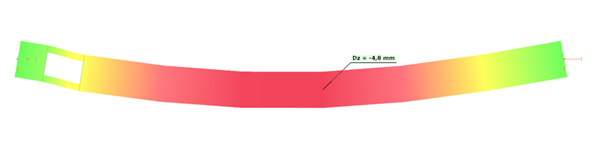
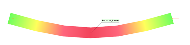
Exposed to a linear load of 10 kN/m, the deflection at mid-span of the solid web beam is 4.6 mm.
Let’s assume that a 250 mm deep rectangular opening with a length of 400 mm needs to be provided on the web, at a distance of 300 mm from the left support.
Traditional analysis with beam finite elements
Consteel 7DOF beam finite elements are very powerful, but cannot consider natively such opening. The usual approach is to build a Vierendeel-type of model, by using additional beam elements with a T shape section „above” and „below” the opening. These additional beam elements are defined eccentrically to the reference line of the solid-web beam.
Eccentricities can be easily defined in Consteel using both smart and traditional link elements.
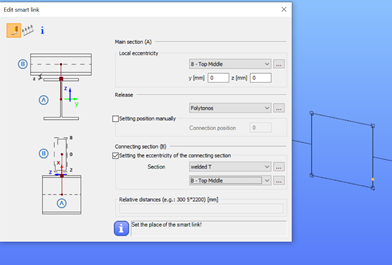
The deflection with this refined model will be equal to 4.8 mm.